
This project demonstrates how to measure four signals for FOC (Field-Oriented Control) using DMA on a Teensy 4. The microcontroller’s two ADC units each sample two channels in a chained configuration, and all signals are filtered with a low-pass filter. A timer triggers the ADC sampling, which makes the sampling asynchronous with the inverter PWM. Because of this, the current sensors must measure the phase currents directly.
This work serves as preliminary development for a future FOC system and has not yet been tested with an actual motor or full FOC implementation.
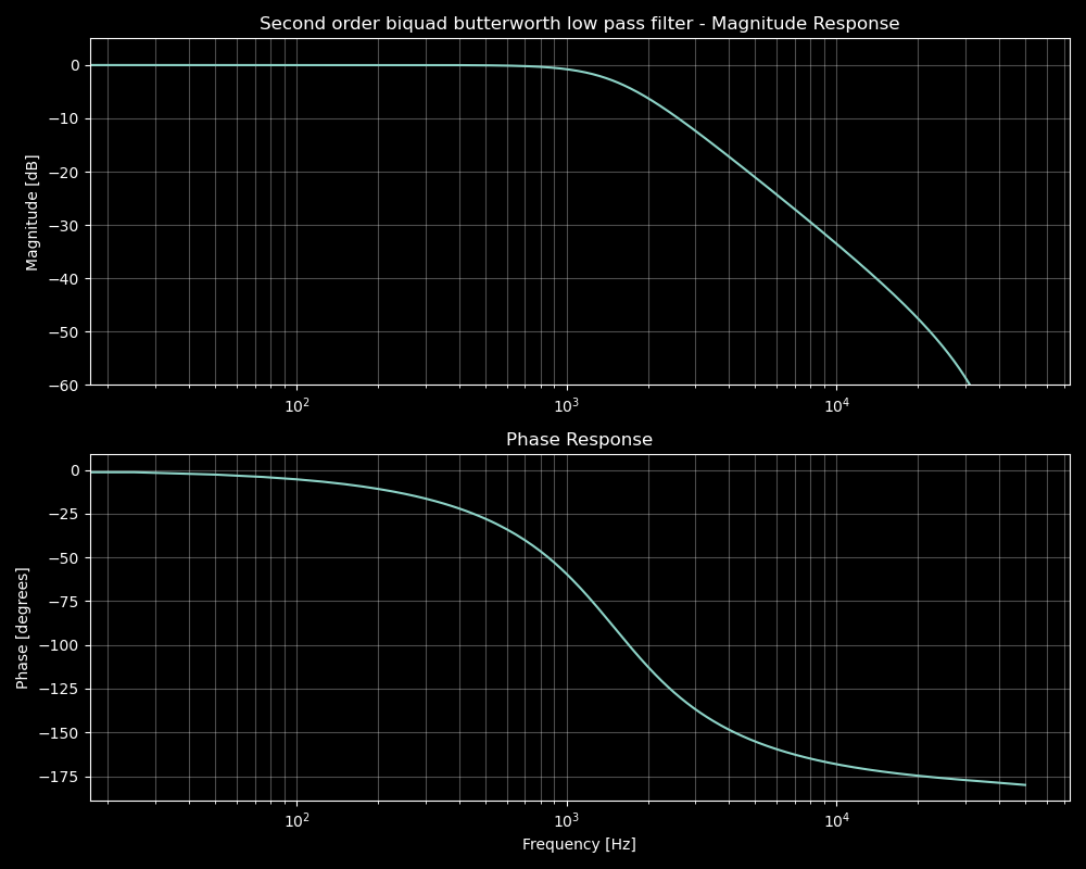
The filter is a second order biquad low pass filter. The sampling frequency is 100 kHz and the corner frequency is 1500 Hz.
/*
Note! Waits for usb serial.
Microcontroller is Teensy 4
Current measurement for three phase inverter where current sensors measure phase currents
This is preparation work and not tested

Operational units/blocks/functions:
Qtimer -> XBAR -> ADC_ETC -> ADC -> DMA -> BUFFER
-Qtimer makes periodic signal at 200 kHz
-XBAR connects Qtimer to ADC_ETC (ADC Enhanced Trigger Control)
-ADC1 and ADC2 are run in sync mode
-Both ADCs use "trigger chains" so that they convert two analog input channels sequentially
(total 4 analog inputs are sampled)
	-Pin 14 UDC (A0) ADC0 group #2
	-Pin 15 IL1 (A1) ADC0 group #1
	-Pin 16 IL2 (A2) ADC1 group #1
	-Pin 17 IL3 (A3) ADC1 group #2
-200kHz and 2 chains -> 100 kHz signal sample frequency
From original code output:
scanned analog inputs per ADCx is 2, #samples is 16
Estimated all 2 per ADC converions time is 1.520 us, f_sample_max = 657894.7 Hz

Code Modified/reduced from https://forum.pjrc.com/index.php?threads/t4-adc-real-time-timer-triggered-with-dma-using-adc_etc.76129/
Qtimer code is from https://github.com/PaulStoffregen/Audio/blob/master/input_adc.cpp
*/

#include "ADC.h" //https://github.com/pedvide/ADC
#include "DMAChannel.h" //https://github.com/PaulStoffregen/cores/blob/master/teensy4/DMAChannel.h

extern "C" {
    extern void xbar_connect(unsigned int input, unsigned int output);
    extern const uint8_t pin_to_channel[];
}

#define CHANNELS_PER_ADC 2
#define N_SAMPLES_PER_INPUT 16
#define DMA_BUFFER_SIZE (CHANNELS_PER_ADC * N_SAMPLES_PER_INPUT)
#define DMA_BUFFER_SIZE_inBytes (DMA_BUFFER_SIZE * 2)
#define OneIterationBytesCount (2*256*CHANNELS_PER_ADC)
#define adc_averaging 2 //adc_averaging - specifies how many ADC samples in a row are averaged before declaring it one new sample
#define adc_nbits 12 //ADC resolution, either 8, 10 or 12

static DMAChannel etc_adc1_dmachannel = DMAChannel();
static DMAChannel etc_adc2_dmachannel = DMAChannel();
DMAMEM __attribute__((aligned(DMA_BUFFER_SIZE_inBytes))) static uint16_t dma_buffer_adc1[DMA_BUFFER_SIZE];
DMAMEM __attribute__((aligned(DMA_BUFFER_SIZE_inBytes))) static uint16_t dma_buffer_adc2[DMA_BUFFER_SIZE];

ADC *adc = new ADC();
int incomingByte = 0;//for serial communication

//Biquad filter
// Filter coefficients for second order butterworth low pass filter. 100 kHz sample frequency and 1500 Hz cutoff
//a0 = 1.000000
const float b0 = 0.002081f;
const float b1 = 0.004161f;
const float b2 = 0.002081f;
const float a1 = -1.866892f;
const float a2 = 0.875215f;

// Biquad filter structure (Direct Form II)
typedef struct {
    float w1;  // Delay element 1
    float w2;  // Delay element 2
} BiquadFilter;

BiquadFilter filter_A0_UDC;
BiquadFilter filter_A1_IL1;
BiquadFilter filter_A2_IL2;
BiquadFilter filter_A3_IL3;
volatile float filtered_A0_UDC;
volatile float filtered_A1_IL1;
volatile float filtered_A2_IL2;
volatile float filtered_A3_IL3;
volatile float A0_UDC;
volatile float A1_IL1;
volatile float A2_IL2;
volatile float A3_IL3;

// Initialize biquad filter
void biquad_init(BiquadFilter* filter) {
    filter->w1 = 0.0f;
    filter->w2 = 0.0f;
}

// Process one sample through the biquad filter
float biquad_process(BiquadFilter* filter, float input) {
    // Direct Form II implementation:
    // w[n] = x[n] - a1*w[n-1] - a2*w[n-2]
    // y[n] = b0*w[n] + b1*w[n-1] + b2*w[n-2]

    float w0 = input - a1 * filter->w1 - a2 * filter->w2;
    float output = b0 * w0 + b1 * filter->w1 + b2 * filter->w2;

    // Update delay elements
    filter->w2 = filter->w1;
    filter->w1 = w0;

    return output;
}

void qtimer4_init() {
  // quad timer used for ADC trigger
	const int comp1 = 750;//200 kHz frequency at 150E6 clock
	TMR4_ENBL &= ~(1<<3);
	TMR4_SCTRL3 = TMR_SCTRL_OEN//The OFLAG output signal is driven on the external pin
		| TMR_SCTRL_FORCE;//force is set here https://github.com/PaulStoffregen/Audio/blob/master/input_adc.cpp
	TMR4_CSCTRL3 = TMR_CSCTRL_CL1(1)//COMP1 is preloaded with the value from CMPLD1 when successful compare with the value in COMP1
		| TMR_CSCTRL_TCF1EN;//Timer Compare 1 Interrupt Enable
	TMR4_CNTR3 = 0;//counter
	TMR4_LOAD3 = 0;//This read/write register stores the value used to initialize the counter after counter compare.
	TMR4_COMP13 = comp1;
	TMR4_CMPLD13 = comp1;
	TMR4_CTRL3 = TMR_CTRL_CM(1) | TMR_CTRL_PCS(8) | TMR_CTRL_LENGTH | TMR_CTRL_OUTMODE(3);//TMR_CTRL_PCS(8) is bus clock
	TMR4_CNTR3 = 0;
	//enable interrupt - for debug
	//attachInterruptVector(IRQ_QTIMER4, qtimer4_isr);
  //NVIC_ENABLE_IRQ(IRQ_QTIMER4);
	TMR4_ENBL |= (1<<3);
}

/*
void qtimer4_isr() {
  static uint32_t cnt=0;
	TMR4_CSCTRL3 &= ~TMR_CSCTRL_TCF1;
  cnt++;
	asm("dsb");
	if (cnt % 200000 == 0) {
		digitalToggleFast(LED_BUILTIN);
	}
}
*/
void dma1_etc_adc_isr()
{
  static int citer;//re-initialized at every execution but perhaps saves a few cycles (which there are a lot in T4 so...)
  arm_dcache_delete(dma_buffer_adc1, DMA_BUFFER_SIZE_inBytes);
  citer = etc_adc1_dmachannel.TCD->CITER & 0x001F;
  if (citer > 8) {//buffer full, read the last half of it
    for (int i = 8; i<16;i++) {
      //order of the chain is A1, then A0 which affects to index
      A0_UDC = (float)(dma_buffer_adc1[i*2+1]-2047);
      filtered_A0_UDC = biquad_process(&filter_A0_UDC, A0_UDC);
      A1_IL1 = (float)(dma_buffer_adc1[i*2]-2047);
      filtered_A1_IL1 = biquad_process(&filter_A1_IL1, A1_IL1);
    }
  } else {
    for (int i = 0; i<8;i++) {//interrupt at half -> read from the beginning to half
      A0_UDC = (float)(dma_buffer_adc1[i*2+1]-2047);
      filtered_A0_UDC = biquad_process(&filter_A0_UDC, A0_UDC);
      A1_IL1 = (float)(dma_buffer_adc1[i*2]-2047);
      filtered_A1_IL1 = biquad_process(&filter_A1_IL1, A1_IL1);
    }
  }
  DMA_CINT = 64; // CAIR
  asm("dsb");
}

void dma2_etc_adc_isr()
{
  static int citer;//re-initialized at every execution but perhaps saves a few cycles (which there are a lot in T4...)
  arm_dcache_delete(dma_buffer_adc2, DMA_BUFFER_SIZE_inBytes);
  citer = etc_adc2_dmachannel.TCD->CITER;
  if (citer > 8) {//buffer full, read the last half of it
    for (int i = 8; i<16;i++) {
      //order of the chain is A2, then A3 which affects to index
      A2_IL2 = (float)(dma_buffer_adc2[i*2]-2047);
      filtered_A2_IL2 = biquad_process(&filter_A2_IL2, A2_IL2);
      A3_IL3 = (float)(dma_buffer_adc2[i*2+1]-2047);
      filtered_A3_IL3 = biquad_process(&filter_A3_IL3, A3_IL3);
    }
  } else {
    for (int i = 0; i<8;i++) {//interrupt at half -> read from the beginning to half
      A2_IL2 = (float)(dma_buffer_adc2[i*2]-2047);
      filtered_A2_IL2 = biquad_process(&filter_A2_IL2, A2_IL2);
      A3_IL3 = (float)(dma_buffer_adc2[i*2+1]-2047);
      filtered_A3_IL3 = biquad_process(&filter_A3_IL3, A3_IL3);
    }
  }
  DMA_CINT = 64; // CAIR
  asm("dsb");
}

void adc_init()
{
  // Configure ADC1 and ADC2
  adc->adc0->setAveraging(adc_averaging);
  adc->adc0->setResolution(adc_nbits);
  adc->adc0->setConversionSpeed(ADC_CONVERSION_SPEED::VERY_HIGH_SPEED);
  adc->adc0->setSamplingSpeed(ADC_SAMPLING_SPEED::VERY_HIGH_SPEED);
  adc->adc0->singleMode();
  adc->adc0->disableInterrupts();
  adc->adc1->setAveraging(adc_averaging);
  adc->adc1->setResolution(adc_nbits);
  adc->adc1->setConversionSpeed(ADC_CONVERSION_SPEED::VERY_HIGH_SPEED);
  adc->adc1->setSamplingSpeed(ADC_SAMPLING_SPEED::VERY_HIGH_SPEED);
  adc->adc1->singleMode();
  adc->adc1->disableInterrupts();

  ADC1_CFG |= ADC_CFG_ADTRG; // Hardware trigger
  ADC1_HC0 = 16; // ADC_ETC channel, 144 int enabled, 16 int disabled
  ADC1_GC &= ~ADC_GC_ADCO; // Continuous conversion disabled, same as adc->adcX->singleMode()
  ADC2_CFG |= ADC_CFG_ADTRG; // Hardware trigger
  ADC2_HC0 = 16; // ADC_ETC channel
  ADC2_GC &= ~ADC_GC_ADCO; // Continuous conversion disabled
}

void adc_etc_init()
{
  IMXRT_ADC_ETC.CTRL = ADC_ETC_CTRL_SOFTRST; // Perform a software reset on ADC_ETC
  asm volatile("dsb"); // Ensure SOFTRST operation is completed
  IMXRT_ADC_ETC.CTRL &= ~ADC_ETC_CTRL_SOFTRST; // Clear SOFTRST
  delay(5);

  // Clear the TSC_BYPASS bit to ensure ADC2 is not occupied by the Touch Screen Controller
  IMXRT_ADC_ETC.CTRL &= ~ADC_ETC_CTRL_TSC_BYPASS; // Clear TSC_BYPASS (bit 30)

  // Enable TRIG[0] for xbar triggering
  IMXRT_ADC_ETC.CTRL |= ADC_ETC_CTRL_TRIG_ENABLE((1 << 0));
  // Configure TRIG[0] for ADC1
  IMXRT_ADC_ETC.TRIG[0].CTRL = ADC_ETC_TRIG_CTRL_TRIG_CHAIN(CHANNELS_PER_ADC - 1);
  // Configure chain for TRIG[0]
  IMXRT_ADC_ETC.TRIG[0].CHAIN_1_0 =
      ADC_ETC_TRIG_CHAIN_B2B0 |
      ADC_ETC_TRIG_CHAIN_CSEL0(pin_to_channel[A1]) |
      ADC_ETC_TRIG_CHAIN_IE0(0) |
      ADC_ETC_TRIG_CHAIN_HWTS0(1) |
      ADC_ETC_TRIG_CHAIN_B2B1 |
      ADC_ETC_TRIG_CHAIN_CSEL1(pin_to_channel[A0]) |
      ADC_ETC_TRIG_CHAIN_IE1(0) |
      ADC_ETC_TRIG_CHAIN_HWTS1(1);

    // Configure TRIG[4] for ADC2 in sync mode with TRIG[0]
    IMXRT_ADC_ETC.TRIG[4].CTRL =
        ADC_ETC_TRIG_CTRL_TRIG_CHAIN(CHANNELS_PER_ADC - 1) |
        ADC_ETC_TRIG_CTRL_SYNC_MODE;

    // Configure chain for TRIG[4]
    IMXRT_ADC_ETC.TRIG[4].CHAIN_1_0 =
    ADC_ETC_TRIG_CHAIN_B2B0 |
    ADC_ETC_TRIG_CHAIN_CSEL0(pin_to_channel[A2] & 0xf) |
    ADC_ETC_TRIG_CHAIN_IE0(0) |
    ADC_ETC_TRIG_CHAIN_HWTS0(1) |
    ADC_ETC_TRIG_CHAIN_B2B1 |
    ADC_ETC_TRIG_CHAIN_CSEL1(pin_to_channel[A3] & 0xf) |
    ADC_ETC_TRIG_CHAIN_IE1(0) |
    ADC_ETC_TRIG_CHAIN_HWTS1(1);
}

void setup_xbar()
{
    CCM_CCGR2 |= CCM_CCGR2_XBAR1(CCM_CCGR_ON); // Enable clock for XBAR
    // Connect TMR4 Timer output to ADC_ETC Trigger input
    xbar_connect(XBARA1_IN_QTIMER4_TIMER3, XBARA1_OUT_ADC_ETC_TRIG00); // Connect Timer to trigger TRIG[0]
    xbar_connect(XBARA1_IN_QTIMER4_TIMER3, XBARA1_OUT_ADC_ETC_TRIG10); // Connect Timer to trigger TRIG[4]
}

void adc_dma_init ()
{
    uint32_t SMOD =  (31 - __builtin_clz(2 * CHANNELS_PER_ADC));;
    uint32_t DMOD = (31 - __builtin_clz(DMA_BUFFER_SIZE_inBytes));
    uint32_t SSIZE = 2;//CHANNELS_PER_ADC
    uint32_t DSIZE = 2;//CHANNELS_PER_ADC

    etc_adc1_dmachannel.begin();
    etc_adc1_dmachannel.source(ADC_ETC_TRIG0_RESULT_1_0);
    etc_adc1_dmachannel.destinationCircular(dma_buffer_adc1, DMA_BUFFER_SIZE_inBytes);
    etc_adc1_dmachannel.TCD->NBYTES = 2 * CHANNELS_PER_ADC;
    etc_adc1_dmachannel.TCD->DOFF = 2 * CHANNELS_PER_ADC;
    etc_adc1_dmachannel.TCD->SOFF = 0;
    etc_adc1_dmachannel.TCD->ATTR = DMA_TCD_ATTR_SMOD(SMOD) | DMA_TCD_ATTR_SSIZE(SSIZE) | DMA_TCD_ATTR_DMOD(DMOD) | DMA_TCD_ATTR_DSIZE(DSIZE);

    etc_adc1_dmachannel.transferCount(N_SAMPLES_PER_INPUT);
    etc_adc1_dmachannel.triggerAtHardwareEvent(DMAMUX_SOURCE_ADC_ETC);
    etc_adc1_dmachannel.interruptAtCompletion();
    etc_adc1_dmachannel.interruptAtHalf();
    etc_adc1_dmachannel.attachInterrupt(dma1_etc_adc_isr, 16);

    etc_adc2_dmachannel.begin();
    etc_adc2_dmachannel.source(ADC_ETC_TRIG4_RESULT_1_0);
    etc_adc2_dmachannel.destinationCircular(dma_buffer_adc2, DMA_BUFFER_SIZE_inBytes);
    etc_adc2_dmachannel.TCD->NBYTES = 2 * CHANNELS_PER_ADC;
    etc_adc2_dmachannel.TCD->DOFF = 2 * CHANNELS_PER_ADC;
    etc_adc2_dmachannel.TCD->SOFF = 0;
    etc_adc2_dmachannel.TCD->ATTR = DMA_TCD_ATTR_SMOD(SMOD) | DMA_TCD_ATTR_SSIZE(SSIZE) | DMA_TCD_ATTR_DMOD(DMOD) | DMA_TCD_ATTR_DSIZE(DSIZE);
    etc_adc2_dmachannel.transferCount(N_SAMPLES_PER_INPUT);
    etc_adc2_dmachannel.interruptAtCompletion();
    etc_adc2_dmachannel.interruptAtHalf();
    etc_adc2_dmachannel.attachInterrupt(dma2_etc_adc_isr, 16);

    etc_adc1_dmachannel.TCD->CITER |= DMA_TCD_CITER_ELINKYES_ELINK;
    etc_adc1_dmachannel.TCD->CITER &= ~DMA_TCD_CITER_ELINKYES_LINKCH_MASK;
    etc_adc1_dmachannel.TCD->CITER |= DMA_TCD_CITER_ELINKYES_LINKCH(etc_adc2_dmachannel.channel);
    etc_adc1_dmachannel.TCD->BITER = etc_adc1_dmachannel.TCD->CITER;
    etc_adc1_dmachannel.TCD->CSR &= ~(DMA_TCD_CSR_MAJORLINKCH_MASK);
    etc_adc1_dmachannel.TCD->CSR |= DMA_TCD_CSR_MAJORLINKCH(etc_adc2_dmachannel.channel) | DMA_TCD_CSR_MAJORELINK;

    ADC_ETC_DMA_CTRL = 1<<0;
    IMXRT_ADC_ETC.CTRL |= ADC_ETC_CTRL_DMA_MODE_SEL;
}

void setup()
{
  Serial.begin(9600);
  while (!Serial) {
   ;  // wait for serial port to connect. Needed for native USB port only
  }
  pinMode(LED_BUILTIN, OUTPUT);
  digitalWriteFast(LED_BUILTIN, HIGH);
	delay(1000);
	digitalWriteFast(LED_BUILTIN, LOW);

  //Initialize filters used for ADC signal filtering
  biquad_init(&filter_A0_UDC);
  biquad_init(&filter_A1_IL1);
  biquad_init(&filter_A2_IL2);
  biquad_init(&filter_A3_IL3);

  Serial.println("Setup ADC with ETC, Timer Trigger and DMA");
  Serial.printf("scanned analog inputs per ADCx is %d, ", CHANNELS_PER_ADC);
  Serial.printf("#samples is %d\n", N_SAMPLES_PER_INPUT);
  adc_init();
  adc_etc_init();
  adc_dma_init();
  setup_xbar ();
  qtimer4_init();
  etc_adc1_dmachannel.enable();
  etc_adc2_dmachannel.enable();
}

void loop()
{
  Serial.print("ADC0 ");
  Serial.print(A0_UDC);
  Serial.print(" ");
  Serial.print(filtered_A0_UDC);
  Serial.print(" A1 ");
  Serial.print(A1_IL1);
  Serial.print(" ");
  Serial.print(filtered_A1_IL1);
  Serial.print(" A2 ");
  Serial.print(A2_IL2);
  Serial.print(" ");
  Serial.print(filtered_A2_IL2);
  Serial.print(" A3 ");
  Serial.print(A3_IL3);
  Serial.print(" ");
  Serial.println(filtered_A3_IL3);
  delay(1000);
}