
PWM is intended for three-phase motors and space vector modulation. Three eFlexPWM submodules are used, with one submodule assigned to each phase. The module clocks of the submodules are synchronized. Main features include:
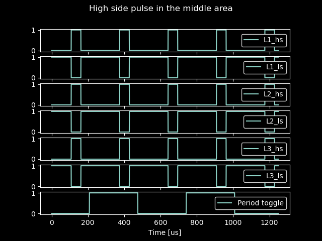
A plot of six PWM signals is shown without deadtime. There is a high-side and low-side signal for each phase. The period toggle is controlled in the PWM interrupt, so both the low and high level display the duration of one PWM period.
Plot showing 10 us deadtime.
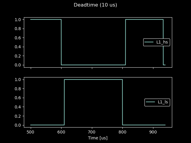
Deadtime is subtracted from the high-side (HS) pulse duration. The following scenarios were tested:
Example of pulses with 150 Mhz clock

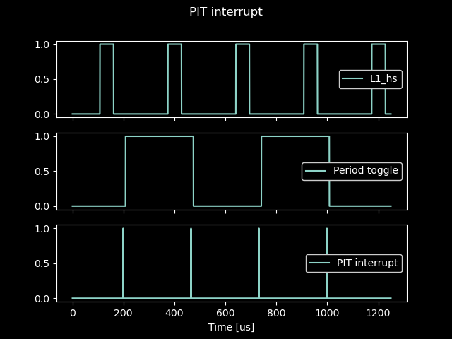
The plot shows the PIT (Periodic Interrupt Timer) and the PWM period. PWM settings are set in the PIT interrupt routine. The PIT and eFlexPWM are synchronized, with the PIT interrupt triggering before the eFlexPWM counter reaches its top value, Val1.
/*PWM for three phase motor control suitable for space vector modulation
Microcontroller is Teensy 4
F_BUS_ACTUAL is 150 MHz. PWM Counter is 16 bit, 65535. without prescaler minimum frequency is about 2,3 kHz
pwm (eflexpwm) is adapted from several threads in PJRC forum, application notes etc.
PWM is complementary mode with deadtime
Note! Code waits for USB serial in setup(), remove it if there is no serial connection.
*/

IMXRT_FLEXPWM_t *flexpwm23 = &IMXRT_FLEXPWM4;  //phase L1 pins 2 and 3
IMXRT_FLEXPWM_t *flexpwm69 = &IMXRT_FLEXPWM2;  //phase L2 pins 6 and 9
IMXRT_FLEXPWM_t *flexpwm87 = &IMXRT_FLEXPWM1;  //phase L3 pins 8 and 7
#define flexpwm23_submodule 2
#define flexpwm23_alt 1
#define flexpwm69_submodule 2
#define flexpwm69_alt 2
#define flexpwm87_submodule 3
#define flexpwm87_alt 6

volatile int test_num = 0;
volatile bool release_PIT = false;
uint16_t DTCNT0 = 0;
uint16_t DTCNT1 = 0;
int incomingByte = 0;  // for incoming serial data

extern "C" {
  extern void xbar_connect(unsigned int input, unsigned int output);
}

/*
setting example
val1 15000 = 100us. 65535 is max
flexpwm23->SM[flexpwm23_submodule].VAL1 = val1;//reload point 150Mhz clock
flexpwm23->SM[flexpwm23_submodule].VAL2 = 0;//starts from 0%
flexpwm23->SM[flexpwm23_submodule].VAL3 = 10000;//ends to 66%

  If the fractional delays are off, then the upper 5 bits of DTCNT0 are ignored and the
remaining 11 bits are used to specify the number of cycles of deadtime. In this case the maximum value
is 0x07FF which indicates 2047 cycles of deadtime. It's the same for DTCNT1.
*/

struct pwm_test_settings {
  uint16_t val1;        //one period, 150 Mhz clock. 15000 = 100 us.
  uint16_t pwm23_val2;  //val2 is start of pulse
  uint16_t pwm23_val3;  //val3 is end of pulse
  uint16_t pwm69_val2;
  uint16_t pwm69_val3;
  uint16_t pwm87_val2;
  uint16_t pwm87_val3;
  uint16_t DTCNT;  //deadtime count. 1500 = 10us
};

//Basic functionality was tested by looping PWM setting which were stored in a stucture
pwm_test_settings pwm_test[7] = {
  { 15000, 0, 10000, 0, 5000, 0, 2500, 0 },                   //pulse from start
  { 20000, 0, 65535, 0, 65535, 0, 65535 },                    //always on
  { 30000, 30000, 30000, 30000, 30000, 30000, 30000, 0 },     //always off. Val2 and val3 can't be higher than val1.
  { 40000, 25000, 33000, 25000, 33000, 25000, 33000, 0 },     //pulse in the middle
  { 50000, 20000, 40000, 20000, 40000, 20000, 40000, 1500},  //pulse in the middle with deadtime
  { 55000, 45000, 55000, 45000, 55000, 45000, 55000, 0 },     //pulse in the end
  { 65535, 0, 10000, 0, 5000, 0, 2500, 0}                    //long period
};

void pit_irq_pwm_control() {
  PIT_TFLG0 = PIT_TFLG_TIF;
  digitalWriteFast(11, HIGH);

  //used to keep PIT interrupt fires at correct amount before flextimer count equals val1
  static uint16_t old_val1;
  static uint16_t pit_prefire_cnt = 1500;  //this PIT interrupt is fired 10us before flextimer reached VAL1, "TOP". 150Mhz clock.

  //pwm clock counts from init (zero) to VAL1 and then restart from init
  uint16_t mask = 1 << flexpwm23_submodule;
  flexpwm23->MCTRL |= FLEXPWM_MCTRL_CLDOK(mask);                      // clear load OK
  flexpwm23->SM[flexpwm23_submodule].VAL1 = pwm_test[test_num].val1;  //reload point 150Mhz clock
  flexpwm23->SM[flexpwm23_submodule].VAL2 = pwm_test[test_num].pwm23_val2;
  flexpwm23->SM[flexpwm23_submodule].VAL3 = pwm_test[test_num].pwm23_val3;
  flexpwm23->SM[flexpwm23_submodule].DTCNT0 = pwm_test[test_num].DTCNT;
  flexpwm23->SM[flexpwm23_submodule].DTCNT1 = pwm_test[test_num].DTCNT;
  flexpwm23->MCTRL |= FLEXPWM_MCTRL_LDOK(mask);

  mask = 1 << flexpwm69_submodule;
  flexpwm69->MCTRL |= FLEXPWM_MCTRL_CLDOK(mask);  // clear load OK
  flexpwm69->SM[flexpwm69_submodule].VAL1 = pwm_test[test_num].val1;
  flexpwm69->SM[flexpwm69_submodule].VAL2 = pwm_test[test_num].pwm69_val2;
  flexpwm69->SM[flexpwm69_submodule].VAL3 = pwm_test[test_num].pwm69_val3;
  flexpwm69->SM[flexpwm69_submodule].DTCNT0 = pwm_test[test_num].DTCNT;
  flexpwm69->SM[flexpwm69_submodule].DTCNT1 = pwm_test[test_num].DTCNT;
  flexpwm69->MCTRL |= FLEXPWM_MCTRL_LDOK(mask);

  mask = 1 << flexpwm87_submodule;
  flexpwm87->MCTRL |= FLEXPWM_MCTRL_CLDOK(mask);  // clear load OK
  flexpwm87->SM[flexpwm87_submodule].VAL1 = pwm_test[test_num].val1;
  flexpwm87->SM[flexpwm87_submodule].VAL2 = pwm_test[test_num].pwm87_val2;
  flexpwm87->SM[flexpwm87_submodule].VAL3 = pwm_test[test_num].pwm87_val3;
  flexpwm87->SM[flexpwm87_submodule].DTCNT0 = pwm_test[test_num].DTCNT;
  flexpwm87->SM[flexpwm87_submodule].DTCNT1 = pwm_test[test_num].DTCNT;
  flexpwm87->MCTRL |= FLEXPWM_MCTRL_LDOK(mask);
  digitalWriteFast(11, LOW);

  //Set next interrupt time
  PIT_TCTRL0 &= ~PIT_TCTRL_TEN;  // Disable Timer 0
  if (release_PIT) {
    //set PIT load value for next interrupt
    PIT_LDVAL0 = old_val1 - flexpwm23->SM[flexpwm23_submodule].CNT - pit_prefire_cnt + pwm_test[test_num].val1;
  } else {
    release_PIT = true;
    //start eflexPWM counting
    mask = 1 << flexpwm23_submodule;
    flexpwm23->MCTRL |= FLEXPWM_MCTRL_RUN(mask);
    mask = 1 << flexpwm69_submodule;
    flexpwm69->MCTRL |= FLEXPWM_MCTRL_RUN(mask);
    mask = 1 << flexpwm87_submodule;
    flexpwm87->MCTRL |= FLEXPWM_MCTRL_RUN(mask);
    //set PIT load value for next interrupt
    PIT_LDVAL0 = pwm_test[test_num].val1 - pit_prefire_cnt;
  }
  PIT_TCTRL0 |= PIT_TCTRL_TEN;  // Enable Timer 0
  //asm volatile ("dsb");
  old_val1 = pwm_test[test_num].val1;
}

void eflexPWM_init() {
  //PWM for three phases is setup here but the counting is not started. Module counting is started
  //in PIT (Periodic Interrupt Iimer), which controls the PWM timer. PIT and eFlexPWM needs to be in sync

  //phase L1 PWM, High side and low side
  uint16_t mask = 1 << flexpwm23_submodule;
  flexpwm23->MCTRL &= ~FLEXPWM_MCTRL_RUN(mask);  // When this bit equals zero, the submodule
  //counter is reset and PWM outputs are held
  flexpwm23->MCTRL |= FLEXPWM_MCTRL_CLDOK(mask);                              // clear load OK
  flexpwm23->SM[flexpwm23_submodule].CTRL |= FLEXPWM_SMCTRL_FULL;             //full cycle reload
  flexpwm23->SM[flexpwm23_submodule].CTRL2 &= ~FLEXPWM_SMCTRL2_INDEP;         //use complementary mode
  flexpwm23->SM[flexpwm23_submodule].TCTRL = FLEXPWM_SMTCTRL_OUT_TRIG_EN(2);  //use val1 as trig1 out

  //Xbar connections. Trig1 out from FlexPWM4 is used as EXT_SYNC in FlexPWM1 and FlexPWM2
  CCM_CCGR2 |= CCM_CCGR2_XBAR1(CCM_CCGR_ON);  //turn clock on for xbara1
  xbar_connect(XBARA1_IN_FLEXPWM4_PWM3_OUT_TRIG1, XBARA1_OUT_FLEXPWM1_PWM3_EXT_SYNC);
  xbar_connect(XBARA1_IN_FLEXPWM4_PWM3_OUT_TRIG1, XBARA1_OUT_FLEXPWM2_PWM2_EXT_SYNC);

  //reload interrupt enable for PWM4, pins 2 and 3
  flexpwm23->SM[flexpwm23_submodule].INTEN = FLEXPWM_SMINTEN_RIE;
  attachInterruptVector(IRQ_FLEXPWM4_2, pwm4_2_isr);
  NVIC_ENABLE_IRQ(IRQ_FLEXPWM4_2);  //IRQ_FLEXPWM4_2 = 149 in imxrt.h
  //reload interrupt set complete

  flexpwm23->OUTEN |= FLEXPWM_OUTEN_PWMA_EN(mask);  // enable A output
  flexpwm23->OUTEN |= FLEXPWM_OUTEN_PWMB_EN(mask);  // enable B output

  //Alternate pin config
  *(portConfigRegister(2)) = flexpwm23_alt;
  *(portConfigRegister(3)) = flexpwm23_alt;

  //phase L2 PWM, High side and low side
  mask = 1 << flexpwm69_submodule;
  flexpwm69->MCTRL &= ~FLEXPWM_MCTRL_RUN(mask);
  flexpwm69->MCTRL |= FLEXPWM_MCTRL_CLDOK(mask);                             // clear load OK
  flexpwm69->SM[flexpwm69_submodule].CTRL |= FLEXPWM_SMCTRL_FULL;            //full cycle reload
  flexpwm69->SM[flexpwm69_submodule].CTRL2 |= FLEXPWM_SMCTRL2_FRCEN;         //init from FORCE OUT enabled
  flexpwm69->SM[flexpwm69_submodule].CTRL2 &= ~FLEXPWM_SMCTRL2_INDEP;        //use complementary mode
  flexpwm69->SM[flexpwm69_submodule].CTRL2 |= FLEXPWM_SMCTRL2_INIT_SEL(3);   //ext sync
  flexpwm69->SM[flexpwm69_submodule].CTRL2 |= FLEXPWM_SMCTRL2_FORCE_SEL(6);  //ext force

  flexpwm69->OUTEN |= FLEXPWM_OUTEN_PWMA_EN(mask);  // enable A output
  flexpwm69->OUTEN |= FLEXPWM_OUTEN_PWMB_EN(mask);  // enable B output

  *(portConfigRegister(6)) = flexpwm69_alt;
  *(portConfigRegister(9)) = flexpwm69_alt;

  //phase L3 PWM, High side and low side
  mask = 1 << flexpwm87_submodule;
  flexpwm87->MCTRL &= ~FLEXPWM_MCTRL_RUN(mask);
  flexpwm87->MCTRL |= FLEXPWM_MCTRL_CLDOK(mask);                             // clear load OK
  flexpwm87->SM[flexpwm87_submodule].CTRL |= FLEXPWM_SMCTRL_FULL;            //full cycle reload
  flexpwm87->SM[flexpwm87_submodule].CTRL2 |= FLEXPWM_SMCTRL2_FRCEN;         //init from FORCE OUT enabled
  flexpwm87->SM[flexpwm87_submodule].CTRL2 &= ~FLEXPWM_SMCTRL2_INDEP;        //use complementary mode
  flexpwm87->SM[flexpwm87_submodule].CTRL2 |= FLEXPWM_SMCTRL2_INIT_SEL(3);   //ext sync
  flexpwm87->SM[flexpwm87_submodule].CTRL2 |= FLEXPWM_SMCTRL2_FORCE_SEL(6);  //ext force

  flexpwm87->OUTEN |= FLEXPWM_OUTEN_PWMA_EN(mask);  // enable A output
  flexpwm87->OUTEN |= FLEXPWM_OUTEN_PWMB_EN(mask);  // enable B output

  *(portConfigRegister(8)) = flexpwm87_alt;
  *(portConfigRegister(7)) = flexpwm87_alt;
}

void periodic_interrupt_timer_init() {

  /*
  setup PIT (Periodic Interrupt Timer) that is used to control eFlexPWM/inverter PWM
  PIT default clock is 24 Mhz but we want to have 150 MHz because eFlexPWM runs at 150 Mhz
  */
  //reference manual p.1010 clock tree: CSCMR1[PRECLK_CLK_SEL], PERCLK_CLK_ROOT
  //pit_ipg_clk is on page 1020. Clock source setting

  //clock has to be disabled before changing the clock, page 1079
  CCM_CCGR1 &= ~CCM_CCGR1_PIT(3);  //this disables both bits
  CCM_CCGR1 &= ~CCM_CCGR1_GPT(3);
  //we can change PERCLK_CLK_ROOT clock source with CSCMR1, register is in page 1052
  CCM_CSCMR1 &= ~CCM_CSCMR1_PERCLK_CLK_SEL;  //derive clock from ipg clk root, default is from osc_clk
  //enable clock with gates
  CCM_CCGR1 |= CCM_CCGR1_PIT(3);  //this enables both bits
  CCM_CCGR1 |= CCM_CCGR1_GPT(3);
  //-> PIT clock is now 150 MHz like eFlexPWM

  // turn on PIT
  PIT_MCR = 0x00;
  // Timer 0
  PIT_LDVAL0 = 10000;
  //PIT_TFLG0 = PIT_TCTRL_TIE;//Timer interrupt enable
  PIT_TCTRL0 = PIT_TCTRL_TIE;   // enable Timer 0 interrupts
  PIT_TCTRL0 |= PIT_TCTRL_TEN;  // Enable Timer 0
  attachInterruptVector(IRQ_PIT, pit_irq_pwm_control);
  NVIC_SET_PRIORITY(IRQ_PIT, 16);  //High priority is must. Only systick has a higher priority
  NVIC_ENABLE_IRQ(IRQ_PIT);
}

void pwm4_2_isr() {
  flexpwm23->SM[flexpwm23_submodule].STS = FLEXPWM_SMINTEN_RIE;
  digitalToggleFast(10);
  asm volatile("dsb");
}

void setup() {
  pinMode(LED_BUILTIN, OUTPUT);
  pinMode(10, OUTPUT);
  pinMode(11, OUTPUT);
  Serial.begin(9600);
  while (!Serial) {
    ;  // wait for serial port to connect. Needed for native USB port only
  }

  eflexPWM_init();
  periodic_interrupt_timer_init();
}

void loop() {
  for (int i = 0; i < 7; i++) {
    test_num = i;
    Serial.print("Test #: ");
    Serial.println(test_num, DEC);

    delay(500);
    Serial.print("PIT_LDVAL0: ");
    Serial.println(PIT_LDVAL0);
    if (test_num % 2 == 0) {
      digitalWriteFast(LED_BUILTIN, HIGH);
    } else {
      digitalWriteFast(LED_BUILTIN, LOW);
    }
  }
}