Voltage boost is a frequency reference modification method designed to maximize the linear modulation range in variable frequency drives (VFDs). It’s particularly useful for pump and fan applications where the power supply uses a three-phase diode rectifier. When the load is highest at the nominal frequency, voltage boost can enhance performance if the maximum linear modulation index range has been reached.
The following provides a brief overview, followed by a numerical/simulation example demonstrating the creation of a voltage boost frequency reference and synchronization angle controller. This example uses a 50 Hz network frequency, though the functionality remains consistent at other frequencies.
Voltage boost relies on three main principles:
The core idea is to synchronize the motor frequency reference with the DC voltage ripple so that the highest DC voltage coincides with the mid-sector of the space vector modulation. This synchronization maximizes the linear modulation range. Given that there are six sectors, a six-pulse rectifier is required for this configuration.
It is assumed that input reactors (on the AC or DC side) and DC capacitors smooth out the pulses, producing a ripple voltage that is roughly sinusoidal. Voltage boost is beneficial when DC voltage is low enough that continuous linear modulation over the full 50 Hz cycle would be otherwise unachievable without synchronized operation.
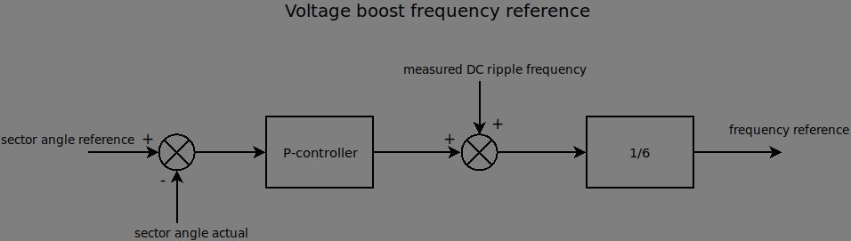
The foundation of the frequency reference is calculated from the DC ripple voltage, with a P-controller used for synchronization.
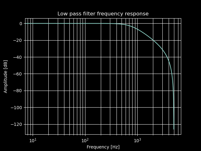
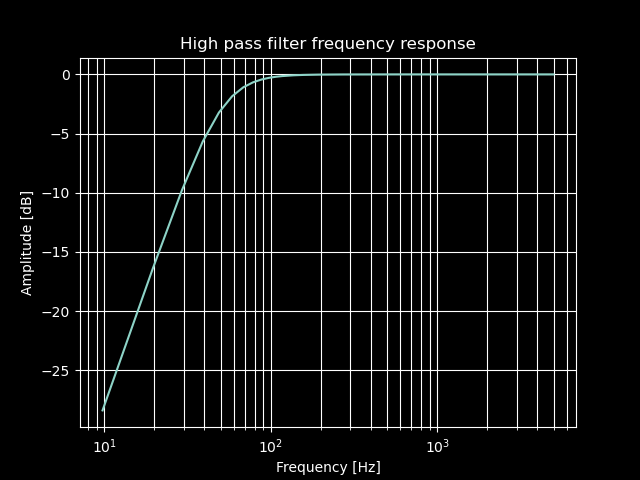
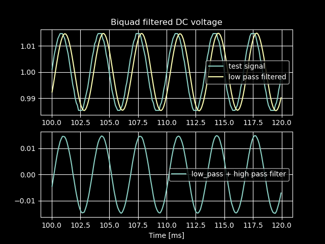
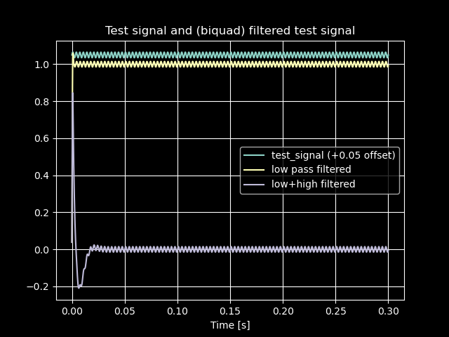
A 300 Hz ripple voltage signal is required to be reasonably noise-free for effective voltage boost. To reduce high-frequency noise, a second-order low-pass filter is applied. The average DC voltage value is then removed using a second-order high-pass filter. Both filters are implemented as IIR biquad filters.
Below is an example of biquad filtering implemented in Python code. The sample frequency is set at 10 kHz, and the test signal simulates a DC voltage signal with a 300 Hz ripple of 3% peak-to-peak amplitude. The DC voltage signal is quantized to 10 bits (1024 steps), which is slightly lower than the resolution typically available on modern microcontroller ADCs. Zero-crossings are detected, and the sector angle signal is sampled at each negative-to-positive transition. Since there is no modulator, the sector angle signal is generated in code.
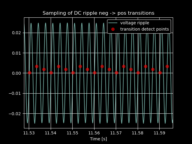
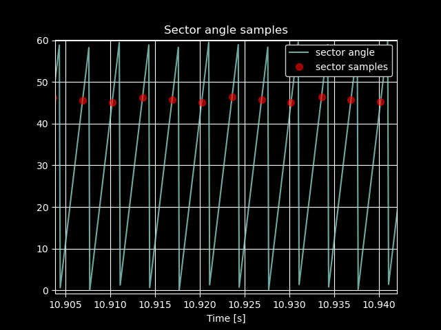
The first plot illustrates the sampling of a filtered voltage signal with a 5% peak-to-peak ripple amplitude. With a sampling frequency of 10 kHz, the zero-crossing transitions from negative to positive are not precisely detected. The calculated frequency, shown in the second plot, is somewhat noisy, so a first-order low-pass filter is applied for smoothing. The filtered signal then serves as the measured DC ripple frequency. In the third plot, the sampling of the sector angle is shown.
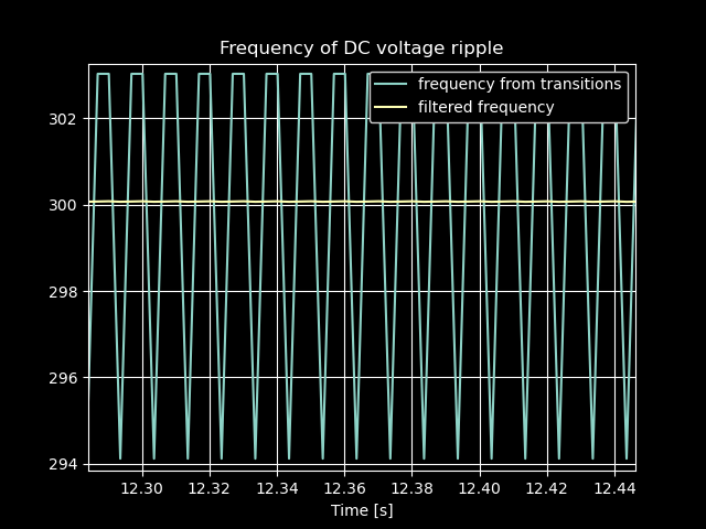
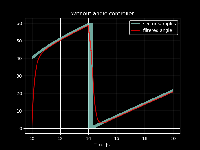
The DC ripple frequency and the sector angle signal frequency are closely matched without a controller, though a slight mismatch remains. Even with perfect frequency matching, phase synchronization is absent. The sector angle signal is smoothed using a first-order low-pass filter. Although wrapping of the sector angle is ignored in filtering, this doesn’t pose an issue for this short test.
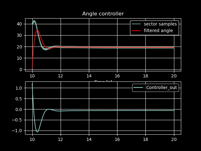
Adding a simple P-controller stabilizes the sector angle, keeping it close to the target reference angle of 18.5°. Due to filtering delays, the reference angle was adjusted from 15°; however, this does not affect the test’s purpose, which is simply to simulate the synchronization process briefly. The goal of this test was to verify the feasibility of achieving synchronized operation.